


“Make the return larger than the supply” is common HVAC advice. It's also incomplete. A large return grille connected to a restrictive filter, undersized transition, crushed flex run, or poorly planned room path can still leave the blower fighting excessive resistance.
Return air duct sizing works when the entire return path is treated as an airflow system. Duct diameter matters, but so do static pressure, grille free area, filter resistance, duct length, bends, and closed-room pressure balance. Those details affect air-conditioning repairs, AC installation, heat-pump performance, furnace operation, equipment noise, and long-term reliability.
Why Return Air Duct Sizing Is About Pressure Not Just Size
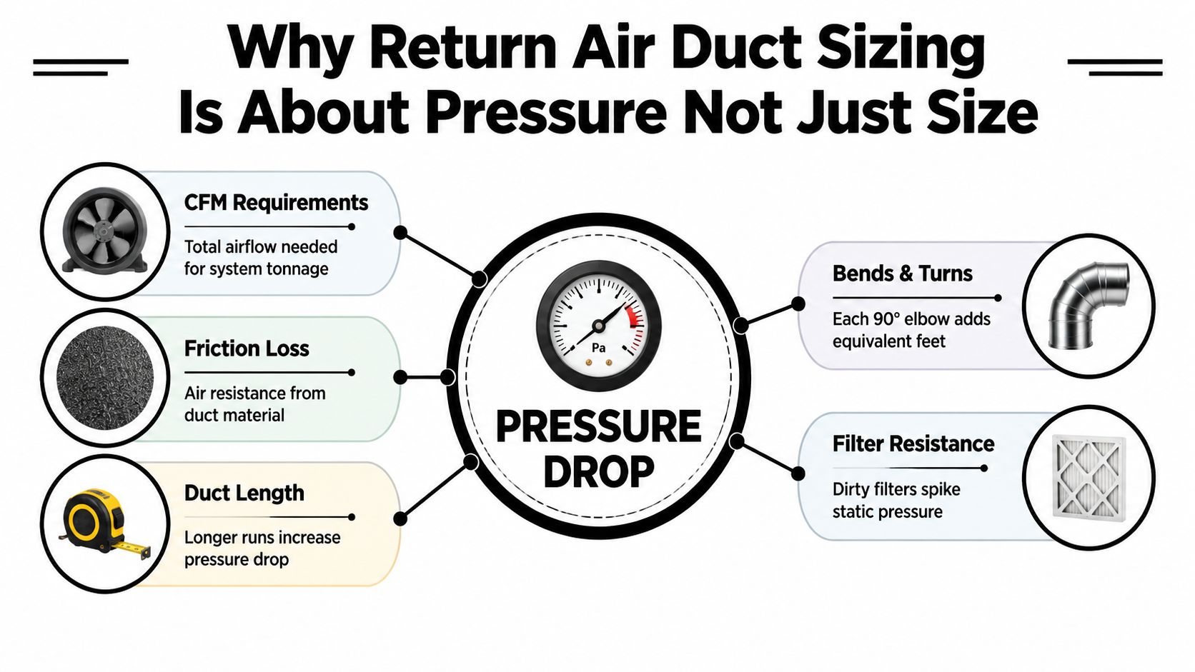
A bigger return duct isn't automatically a better return. Increasing diameter can reduce friction, but it won't correct a restrictive grille, a dirty filter, a sharp transition, or a bedroom with no path back to the air handler. In some layouts, oversizing a section can also reduce velocity enough to make the duct arrangement inefficient without solving the actual bottleneck.
The practical target is controlled pressure drop from the return grille to the blower inlet. ACCA Manual D uses a lower design friction rate for return ducts than for supply ducts, 0.05 inches of water column per 100 feet for returns versus 0.08 inches for supplies, because the return side needs low resistance to move the required airflow efficiently. ACCA Manual D guidance connects return design with fan static pressure, airflow, and noise.
The pressure budget includes more than ductwork
A return system can fail at the grille before air reaches the duct. A filter with high resistance, a small filter rack, or a grille with limited free area can consume much of the available pressure budget. That's why a technician should measure the installed system instead of judging performance by duct diameter alone.
Return velocity also matters. Low-noise applications commonly cap return-air velocity around 700 feet per minute, while many design references keep main return trunks in the 600 to 900 feet-per-minute range to balance noise and pressure loss, as summarized in ACCA Manual D and related return-path design guidance. ASHRAE-related examples place return-path velocities around 575 to 800 feet per minute, depending on elbows, grilles, and other fittings, with the assembly intended to hold pressure drop near 0.08 inches of water column.
Field rule: Size the return for the airflow the equipment needs, then verify that the filter, grille, fittings, and duct route stay within the equipment's pressure limits.
Core Variables That Determine Return Duct Dimensions
Return sizing starts with the airflow the equipment must move, then works backward through the pressure budget. Cooling tonnage offers only a starting point. The manufacturer's airflow table and a proper load calculation should set the target, because an oversized system can make a tonnage-based rule of thumb misleading. For the broader equipment-sizing process, see this guide to how to size an HVAC system.
ACCA Manual D's framework for duct dimension selection combines airflow, friction rate, velocity, and equivalent length. The return duct is only one part of that calculation. The filter rack, grille, transitions, dampers, elbows, and the route itself all consume available pressure.
| Variable | Typical Residential Range | Impact on Duct Size |
|---|---|---|
| Return friction rate | 0.05 in. w.c. per 100 ft for returns | Lower friction generally requires a larger duct or a shorter, straighter route |
| Main return velocity | 600 to 900 fpm | Higher velocity can increase noise and pressure loss |
| Low-noise return velocity | Around 700 fpm or less | Usually calls for more free area |
| Return-path examples | 575 to 800 fpm | Fittings and grilles influence the final pressure drop |
| Assembly pressure-drop reference | Near 0.08 in. w.c. | Helps evaluate the complete return path |
Four measurements that control the choice
Airflow demand: Establish the CFM required by the air handler, furnace, air conditioner, or heat pump. For heat pumps, BPI technical standards specify measured airflow between 375 and 450 CFM per ton, or the manufacturer's specification when measured over a dry coil in heating mode.
Available friction: Count the pressure cost of the complete route. Long runs, elbows, transitions, dampers, filters, and grilles cannot be treated as free components. A compact duct may look adequate while the assembled system still starves the blower.
Velocity: Reasonable air speed helps control whistling and turbulence. Increase duct area when the required CFM would otherwise force air through a narrow, high-speed path.
Grille free area: Nominal grille dimensions do not equal the open area available to airflow. A practical starting rule is about 2 CFM per square inch of return opening, as described in residential duct sizing guidance from CED Engineering. Louvers and filters reduce usable area, so the grille manufacturer's data should control the final selection.
Review the route before installation. For single-return systems, energy-code return duct guidance limits return runs to 30 feet and 180 degrees of total bend, and requires at least one metal elbow when total bending exceeds 90 degrees. These limits steer the design away from long, sharply bent paths that pass a simple area calculation but create excessive field pressure loss.
Calculating Return Duct Size From Tonnage to Dimensions
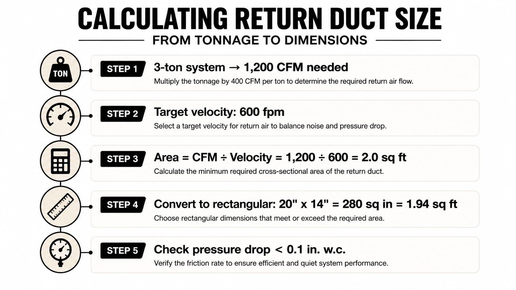
A worked example helps, provided it's treated as a design illustration rather than a substitute for the equipment data. Consider a 3-ton system requiring 1,200 CFM of total return airflow. The first step is to select a reasonable design velocity and calculate the cross-sectional area.
At 600 feet per minute, the required area is:
1,200 CFM ÷ 600 fpm = 2.0 square feet
That equals 288 square inches. A rectangular option of 20 by 14 inches provides 280 square inches, or about 1.94 square feet, so it's close to the calculated area. The final choice would need to account for the actual grille, filter, transitions, duct material, fittings, and manufacturer requirements.
Use the calculation as a screening tool
The area calculation identifies a starting dimension. It doesn't prove that the installation will deliver rated airflow. A designer still needs to:
- Select the friction rate: Use the return-side design friction rate and the duct sizing chart associated with the selected system.
- Account for equivalent length: Include the two 90-degree elbows, the filter grille, transitions, and any other fitting that changes direction or shape.
- Check the pressure drop: A packaged-system technical note designs return pressure drop at 0.15 inches of water column including filter pressure drop, and states that combined duct and filter resistance must remain below that limit. The technical note is available from Unico.
- Compare with equipment data: The air handler or furnace manufacturer's external-static-pressure limit controls. Don't assume a generic limit applies to every blower.
- Verify the installed result: Measure external static pressure and airflow after installation.
The same CFM can move through different shapes. A round duct, a rectangular trunk, or multiple return branches may all work, but the route and fittings determine whether the design performs. HVAC duct design guidance is useful when a project needs more than a simple area calculation, especially during AC installation or a system replacement.
Room by Room Return Path Design and Pressure Balance
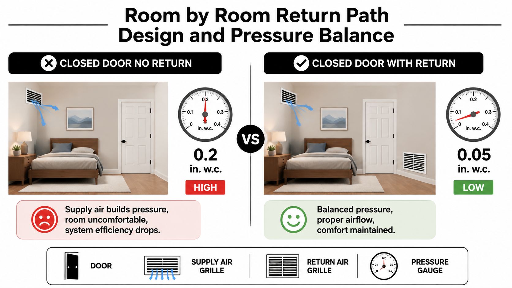
A central return can be large enough for the whole system and still leave a closed bedroom uncomfortable. Supply air enters the room, the door closes, and the room has no low-resistance route for air to reach the return. Pressure rises inside the room, airflow falls, and the air handler may see less return volume than the duct-size calculation promised.
Building America guidance on ducted returns addresses this overlooked room-by-room problem. The practical question is whether each occupied room has a reliable return path, not merely whether the hallway grille looks large.
Three ways to create the path
Dedicated return duct: A return grille connects directly to the return system. This provides the clearest airflow route and can reduce pressure transfer between rooms, but it costs more and requires careful placement and filter coordination.
Transfer grille: A grille in the wall or door allows air to move toward a central return. It's often practical during remodeling, though it can transmit sound and must have enough free area for the room's airflow.
Jumper duct: A short duct connects the bedroom or enclosed space to a hall or adjacent return area, usually through the ceiling or attic route. It often works well in retrofits because it avoids cutting a full dedicated return back to the air handler.
ACCA design practice commonly uses a room pressure limit around 0.01 inches of water column, but the installed result should be measured with doors closed rather than assumed from a drawing. A door undercut may look convenient, yet its effective free area depends on the gap, door width, grille restrictions, and the airflow crossing it.
A return path that works with the door open isn't necessarily a return path that works in daily life.
Common Return Duct Sizing Mistakes and How to Avoid Them
The same installation problems appear repeatedly during AC repairs and furnace service calls. Most aren't caused by one wrong duct diameter. They come from ignoring the combined resistance of the return assembly or treating room pressure as someone else's problem.
| Mistake | Consequence | Correct Approach |
|---|---|---|
| Undersizing the main return trunk | Higher static pressure, blower strain, noise, and reduced airflow | Use the required CFM, return friction rate, fitting count, and equipment pressure limit |
| Ignoring filter resistance | The filter becomes a hidden restriction that can dominate return pressure loss | Include the filter and rack in the pressure budget, then measure pressure drop in operation |
| Relying on one central return in a multi-room layout | Closed rooms can become pressurized and develop uneven comfort | Add dedicated returns, transfer grilles, or jumper ducts where testing shows a blocked path |
| Oversizing to compensate for a poor route | A larger duct may not fix sharp bends, crushed flex, or a restrictive grille | Correct the route and fittings instead of adding diameter blindly |
| Neglecting grille free area | The grille or louver throttles airflow even when the duct itself is adequate | Size the grille by usable free area and confirm its pressure-drop data |
The filter deserves special attention
A filter protects the equipment and supports indoor air quality, but it also adds resistance. CED Engineering's return duct design discussion emphasizes that a return can satisfy basic CFM math and still fail when the filter, grille, bends, or long run push external static pressure too high.
Don't close supply registers to “force” air elsewhere. That changes system resistance and can make an existing airflow problem worse. Keep furniture, curtains, and storage away from return grilles, and make filter access straightforward enough that maintenance won't be postponed.
Testing and Inspecting Your Return Air System After Installation
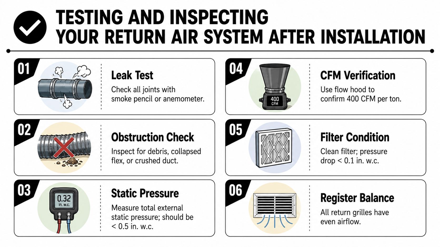
A duct calculation is only a prediction until the installed system is tested. A technician should inspect the return path for leaks, crushed flex, debris, disconnected joints, blocked grilles, and an improperly fitted filter. Duct sealing guidance from Cobre Valley Air's ductwork resource can help identify why a sound design may still lose performance after installation.
Use this field checklist:
- Inspect the physical route. Look for sharp kinks, collapsed flexible duct, loose insulation, and obstructed returns.
- Measure total external static pressure. Use a manometer at the air handler and compare the result with the manufacturer's rated limit. Many residential systems are evaluated around 0.5 inches of water column or less, but the equipment documentation controls.
- Check room pressure. Close bedroom doors and measure pressure across the door. A reading above 0.01 inches of water column indicates that the return path needs attention, based on the room-balance guidance discussed earlier.
- Measure grille airflow. A flow hood or Velgrid can show whether each return contributes its intended share.
- Evaluate the filter. Check fit, loading, rack size, and measured pressure drop. A technical inspection target may use filter pressure drop below 0.1 inches of water column, but filter type and equipment specifications still apply.
- Test leakage where appropriate. A duct blaster and blower-door combination can evaluate leakage to unconditioned space. ENERGY STAR-oriented testing may target less than 4% leakage to unconditioned space, as reflected in the inspection criteria provided for this system.
A seasonal check is useful after filter changes, especially when the system has a variable-speed blower, heat pump, or a history of airflow complaints. The filter that worked during commissioning may create more resistance as it loads with dust.
Putting It All Together for a Right-Sized Return System
A reliable return design follows a clear order:
- Establish the equipment's required airflow from load calculations, manufacturer data, and operating mode.
- Allocate return capacity across the home instead of assuming one hallway grille serves every room.
- Select duct dimensions using airflow, friction rate, velocity, equivalent length, and grille free area.
- Include filter resistance and transitions in the pressure budget.
- Provide a return path for rooms with closed doors through dedicated returns, transfer grilles, or jumper ducts.
- Test external static pressure, grille airflow, leakage, and room pressure after installation.
The right return system doesn't just move air back to the blower. It keeps the air handler, AC coil, heat pump, or furnace operating within its design envelope while maintaining a usable path from every conditioned space. A return that's too restrictive can contribute to noise, weak airflow, coil problems, short cycling, and premature equipment wear, while an incomplete room path creates comfort complaints that a larger central grille may never solve.
For homeowners, builders, and property managers, the best proposal is one that shows the airflow target, duct route, filter arrangement, grille free area, and verification plan. Cobre Valley Air LLC provides duct design, repair, inspection, airflow evaluation, AC installation, maintenance, and HVAC diagnostics for homes and businesses in Globe, Miami, Superior, and nearby Arizona communities.
Visit Cobre Valley Air LLC to schedule a return-air evaluation, AC repair, installation review, or duct inspection. Their technicians can measure airflow and static pressure, identify restrictive return paths, and recommend a practical correction for your system.