


The Installation Is Not Finished at Startup
The most popular HVAC advice is also the most incomplete: choose a new unit, install it, turn it on, and call the job done. A system can start normally and still deliver poor comfort, waste energy, leak conditioned air, or create expensive repair problems when sizing, duct design, permits, airflow, refrigerant work, or customer handover gets skipped.
A reliable HVAC installation checklist follows the work in order, from load calculation and equipment selection through commissioning and acceptance. It applies to AC installation, quality air conditioning repairs, AC maintenance planning, heat pumps, furnaces, ductless mini-splits, rooftop units, and walk-in coolers. Arizona conditions make the details more demanding, especially in Globe, Miami, Superior, and nearby communities where heat, dust, attic temperatures, and long cooling seasons expose weak installations quickly.
Modern checklists also connect field work to code and manufacturer requirements. UL's HVAC installation and inspection guidance ties verification to UL 60335-2-40, IRC-2024, IMC-2024 or UMC-2024, and ASHRAE 15-2022, depending on the installation pathway. That makes the checklist a milestone map, not a paperwork exercise.
A contractor such as Cobre Valley Air LLC can bring the same sequence to diagnostics, airflow evaluation, duct planning, code-compliant installation, and service-focused handover. The following ten steps show what should be verified before, during, and after the equipment is installed.
1. System Sizing and Load Calculation
A right-sized HVAC system begins with a documented load calculation, not a guess based on floor area or the capacity of the old unit. AC installation planning should account for insulation, window orientation, solar exposure, air leakage, occupancy, equipment heat, building use, and the local Arizona climate. A new home in Globe, a restaurant kitchen, and an addition to an existing house don't have the same cooling or heating profile.
ACCA identifies Manual J 8th Edition as the ANSI-recognized residential sizing standard, and it's required by national building codes and most state and local jurisdictions for proper residential load calculations. The result guides air-conditioning capacity, furnace output, and heat-pump selection. An undersized system may run continuously during severe heat, while an oversized system can cycle too quickly and manage humidity poorly.
What the calculation must answer
Ask for the calculation in writing before approving equipment. It should show how the contractor translated building conditions into required capacity, not just recommending a familiar tonnage.
- New construction: Confirm that the calculation is complete before equipment is selected and duct routes are finalized.
- Commercial spaces: Account for cooking equipment, refrigeration, occupancy, ventilation, and operating schedules. A restaurant kitchen has a very different heat load from a light commercial office.
- Additions and renovations: Recalculate the affected structure. Extending an existing system without checking available capacity can create weak airflow and uneven temperatures.
- Future changes: Discuss planned additions, insulation upgrades, or room conversions, but don't pay for capacity that the verified load doesn't support.
Practical rule: A brand name, a larger cabinet, or the capacity of the previous system isn't a substitute for a load calculation.
Cobre Valley Air LLC's HVAC sizing guidance is a useful starting point for homeowners preparing questions. Use the calculated load to compare Goodman, Amana, or Daikin options, then verify that the selected equipment, duct system, and electrical service can support the result.
2. Ductwork Design, Sealing, and Air Leakage Control
A new HVAC unit cannot overcome a restrictive or leaky duct system. Before routes are approved, verify supply and return sizes, fitting locations, support, insulation, and access for later inspection. Arizona projects need added attention in attics, where extreme heat and dust can affect duct performance before conditioned air reaches occupied rooms.
Use the friction-loss method described in ASHRAE's duct-design material, including equivalent length from elbows, transitions, and other fittings. Confirm that the design can deliver required airflow at the farthest outlets without excessive noise or resistance. Returns also need a clear air path. A starved return can reduce comfort and increase system strain.
Seal before the walls close
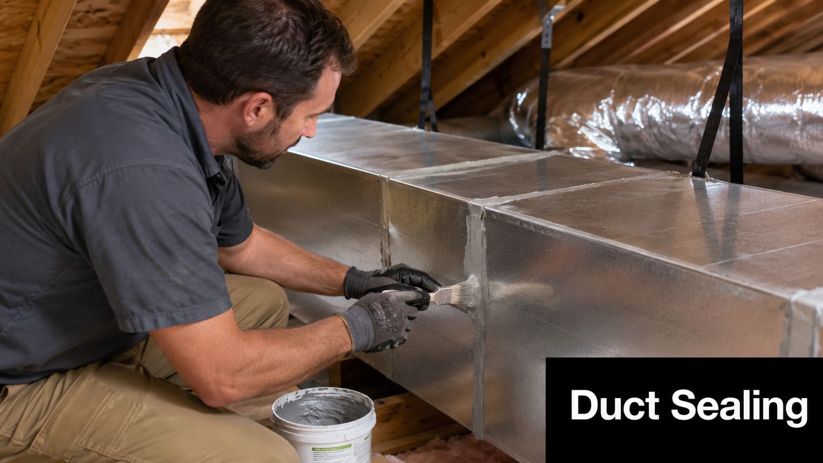
Set duct routes before framing closes in new construction. Keep access panels, dampers, and service points reachable after finishes are installed. Seal joints with HVAC-grade mastic, using fiber mesh reinforcement where the joint requires it. Metal-backed, UL-listed tape can finish exposed mastic, while ordinary cloth duct tape should not be treated as a permanent repair.
- Supply paths: Keep runs direct where practical, support flexible duct correctly, and provide dampers for balancing rooms or zones.
- Return plenums: Seal every joint, especially near hot attics or dusty mechanical spaces, and verify that grilles and pathways are large enough for the intended airflow.
- Insulation: Repair crushed or missing insulation and protect exposed ductwork from physical damage and condensation.
- Testing: Check for leakage before close-in and after sealing with smoke, a blower-door approach, or applicable duct-leakage testing.
The professional duct design and evaluation guidance from Cobre Valley Air LLC can help homeowners and operators frame questions about new routes, repairs, inspection, and balancing. In Arizona, schedule attic sealing during cooler morning or evening hours when possible, and document inaccessible sections before they are covered.
For a measurable quality target, the ENERGY STAR HVAC Quality Installation Guidebook lists total duct leakage at ≤ 6 CFM25 per 100 square feet of conditioned floor area and outdoor leakage at ≤ 5 CFM25 per 100 square feet in its rater checklist. Record the test method and results in the handover file.
A short visual demonstration can reinforce why joint preparation and complete coverage matter:
3. Equipment Selection and Compatibility Verification
Equipment selection starts with the approved combination, not the outdoor condenser. Confirm that the indoor coil, air handler or furnace, metering device, controls, and outdoor unit are listed to operate together by the manufacturer. An unmatched combination can change capacity, efficiency, control behavior, warranty support, and fault diagnosis.
Choose equipment for the building and its operating conditions. A residence may use a conventional air conditioner and furnace, a heat pump, or a ductless mini-split. Central heat pumps suit many new homes, while an addition without a workable duct route may need ductless equipment. Restaurants often require rooftop units built for sustained commercial service. A walk-in cooler needs refrigeration equipment intended for continuous temperature control, not comfort-cooling equipment.
Compare the whole ownership decision
Purchase price is only one part of the decision. Service access, replacement parts, control familiarity, and compatibility with the building can determine the system's long-term value.
- Match the application: Review occupancy, operating hours, internal heat sources, zoning, and the required heating method. For rooftop units, verify curb dimensions, service clearances, economizer requirements, and roof loading. For ductless mini-splits, confirm indoor-unit type, line-set limits, condensate routing, and outdoor-unit placement. Walk-in cooler selections also require checking box temperature, door use, defrost method, and condenser conditions.
- Confirm the rating: A residential Goodman system marketed at SEER2 16+ must be evaluated as a matched system, not by the outdoor label alone. Check the certified combination and the expected operating conditions.
- Check desert conditions: Where the design requires it, account for Arizona's 120°F+ summer heat and confirm the manufacturer's operating limits. Rooftop units and outdoor condensers need adequate airflow and service access when exposed to intense heat.
- Review the documents: Obtain model numbers, matched-system data, installation requirements, warranty terms, electrical information, and service contacts before purchase.
- Plan for service: Goodman, Amana, and Daikin equipment may be practical choices when local technicians support the selected combination and understand its controls.
Equipment availability should not override compatibility. If a substitute is proposed, require written confirmation that the replacement preserves the approved combination, controls, capacity, and installation requirements.
A heat pump also needs a documented heating strategy. An OSTI report on heat-pump operation notes that the balance or switching point commonly falls between about -10 C and -15 C, below which supplemental heating may be needed to meet the load. In Arizona, that consideration may matter more in mountain or high-elevation locations than in every low-desert application. Record the design assumptions instead of applying one heating rule to every property.
4. Permits, Inspections, and Code Compliance Documentation
Cooling performance does not prove compliance. Before scheduling the crew, confirm the applicable Arizona Building Code, local jurisdiction rules, electrical requirements, refrigerant regulations, and manufacturer instructions. Permit requirements depend on the project and location, so the owner or general contractor should establish the approval path before equipment arrives.
A new build may require mechanical and electrical permits, rough-in coordination, and final inspections. In Superior, a replacement that adds a circuit could trigger an electrical inspection. A commercial restaurant may also require coordination with health or building officials because ventilation, cooking, refrigeration, and occupancy requirements intersect.
Create the project file before work begins, then update it at each milestone:
- Approval stage: Keep the permit application, contractor details, equipment specifications, and planned inspection points.
- Construction stage: Photograph concealed ductwork, line-set routes, supports, drains, disconnects, and equipment labels before walls or ceilings are closed.
- Inspection stage: Retain inspection results, correction notices, approvals, and final permit-closure documents.
- Refrigerant work: Confirm that technicians handling refrigerants hold current EPA Section 608 certification where required.
- Commercial work: Determine whether health department or another agency must review the equipment or occupied space.
UL's code-focused checklist guidance connects model codes, equipment certification, and manufacturer instructions. Use that relationship when checking split systems, ductless mini-splits, rooftop units, or walk-in cooler installations. A licensed, bonded Arizona contractor should provide license information for review. Cobre Valley Air LLC lists Arizona license ROC 339078 in its company information, but the property owner should independently verify the contractor and project documents for the specific job.
Before closeout, match the installed model and serial numbers to the approved documents, resolve every inspection correction, and store the final approvals with the warranty and commissioning records.
5. Refrigerant Line Installation and Evacuation
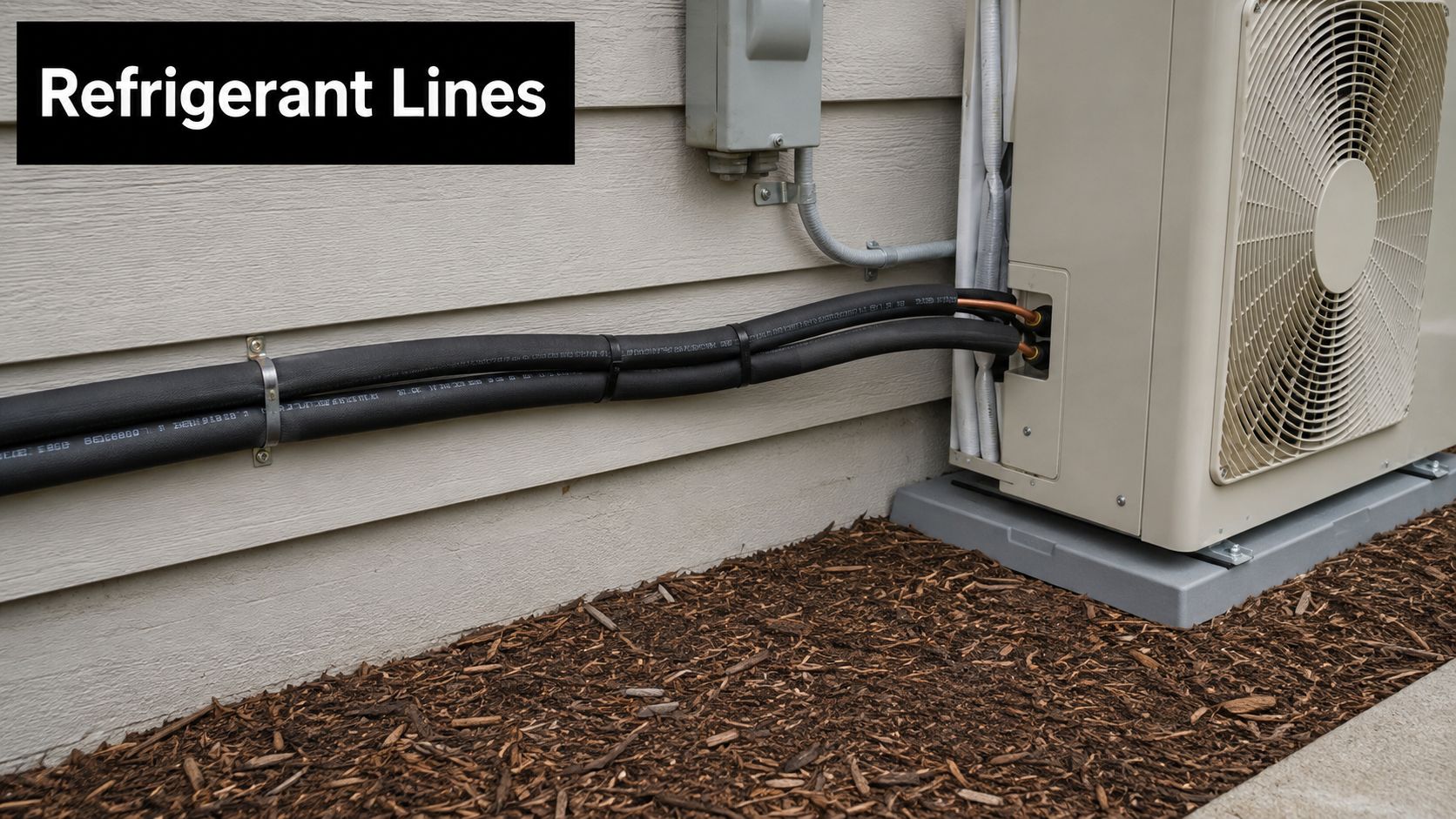
A refrigerant line set can pass a visual inspection and still compromise the system. Confirm the tubing size against the matched indoor coil and outdoor unit, then check the route for kinks, sharp bends, vibration points, and impact exposure. Long runs, roof routes, wall penetrations, and multiple indoor heads require closer review because each connection adds a possible leak or contamination point.
Keep tubing ends capped until connection. Support the lines so their weight and movement do not load the fittings, and seal every wall or roof penetration after routing. Insulate the required lines continuously, including exposed sections. Arizona sun and heat can degrade damaged insulation and increase the system's operating burden.
Evacuation is a measured process, not a verbal assurance. After brazing and pressure testing are complete, connect suitable recovery and evacuation equipment, then use a micron gauge to verify the result. Perform the final evacuation as late as practical so the circuit does not remain open during other construction work. Record the final micron-gauge reading with the commissioning documents.
Match the line work to the equipment
For a split-system replacement, compare the existing line set with the new manufacturer requirements before deciding whether reuse is acceptable. A ductless mini-split with multiple heads needs correctly connected refrigerant lines and controls for every zone. A walk-in cooler may have a longer run to its outdoor condenser, making support, insulation, oil return, and allowable length limits part of the documented review. Rooftop equipment also needs protection from roof traffic and weather exposure.
Before charging or releasing the system, document:
- Refrigerant identification: Record the refrigerant type and confirm that the equipment and service procedures match it. Guidance on whether Freon is still used can help homeowners understand why the actual refrigerant must be identified.
- Charge calculation: List the factory charge, line length, added amount, and final charge weight. Do not accept a guessed charge.
- Connection condition: Check brazed or flared joints for leaks after pressure testing, and keep the line set protected until the circuit is closed.
- Handover evidence: Retain the evacuation result, pressure-test record, refrigerant details, and any adjustment made during startup.
A line set left unprotected, an unrecorded evacuation, or an undocumented charge leaves the installation difficult to verify and service.
6. Electrical Connections and Circuit Verification
Electrical verification starts before equipment arrives. Compare the unit's nameplate data, voltage, minimum circuit ampacity, maximum overcurrent protection, starting method, and control requirements with the building's service. According to the National Electrical Code, a service upgrade may be required when replacement equipment draws significantly more amperage than the original system.
Confirm panel capacity, available breaker space, grounding, and conductor routes during planning. In Arizona, outdoor components also need protection from intense sun, moisture, physical impact, and roof service traffic. Split systems commonly need a dedicated outdoor circuit. A ductless mini-split may require wiring for several indoor heads and their controls. Rooftop units need clearly identified circuits coordinated with roof access. A walk-in cooler may require separate power for the condensing unit, evaporator, heaters, fans, or controls, depending on the equipment design.
Check the installation at the disconnect and unit
Have an appropriately licensed electrician complete electrical work and coordinate the verification with the HVAC installer. Before normal operation, confirm voltage at the disconnect and equipment, match the breaker and conductors to the nameplate, tighten terminations to manufacturer requirements, and test safety controls.
Use the startup record to capture:
- Panel condition: Document service capacity, grounding, breaker space, and the proposed equipment load.
- Disconnect access: Verify that the disconnect is visible, reachable, labeled, and rated for the outdoor location.
- Measured voltage: Record readings at the equipment before startup and during operation when required by the commissioning procedure.
- Physical protection: Inspect conduit, fittings, wiring, and seals for sun exposure, moisture, impact, and interference with service work.
- Commercial identification: Label rooftop circuits and controls so the property manager or technician can isolate the correct unit.
- Inspection record: Retain electrical sign-off and note any correction made before acceptance.
Abnormal voltage, loose connections, or an undersized circuit can cause nuisance trips, compressor damage, weak performance, or unsafe heating behavior. Resolve those findings before handover rather than waiting for a failure. The final file should include equipment data, circuit details, measured readings, and inspection documentation.
7. Drain Line Installation and Condensation Management
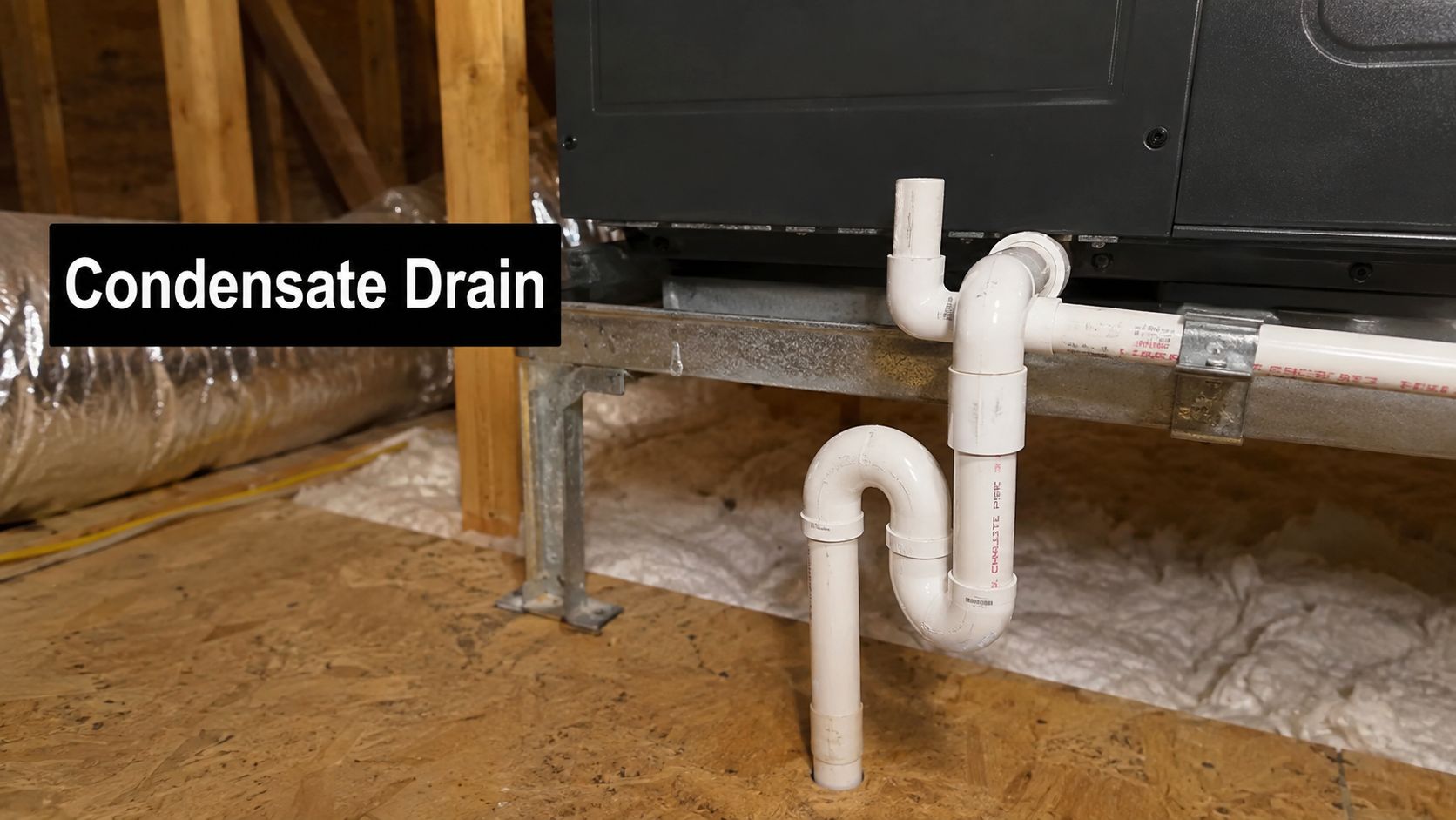
Arizona's dry climate does not prevent condensate. Cooling coils remove moisture whenever warm indoor air crosses a cold surface, and the water needs a controlled route away from ceilings, walls, foundations, equipment, and electrical components. Verify the route during installation, not only during a short startup test. A drain can appear functional while holding water because of poor slope, a blocked trap, an inaccessible termination, or an incorrectly arranged pump.
For gravity drainage, maintain a continuous slope of at least 1/4 inch per foot toward the approved termination. Install a visible, serviceable cleanout and confirm that the trap matches the equipment manufacturer's requirements. A condensate safety switch, such as a RectorSeal Safe-T-Switch SS2 installed where appropriate, can shut down cooling when water rises. It does not correct an undersized line, a missing trap, or a termination that discharges into a damaging location. Follow the applicable IPC or IRC condensate provisions and local amendments, especially for equipment above finished space.
Verify the installation by equipment type
An attic split system may require a secondary pan and conspicuous secondary termination. A basement unit may discharge to a sump pump. Each indoor head on a ductless mini-split needs a properly supported drain, while a rooftop unit needs weather-protected routing that remains accessible for service. A walk-in cooler can produce sustained condensate, so size and route its drain for the expected operating and humidity load.
- Protect the structure: Place primary and secondary outlets where leakage is visible and cannot damage finished areas.
- Preserve access: Keep cleanouts, traps, pumps, and float switches reachable without dismantling unrelated equipment.
- Prevent conflicts: Separate condensate from electrical panels, control boxes, walkways, and foundation edges.
- Test drainage: Pour water through each drain, confirm free flow, then observe the system during sustained operation. Verify that a float switch interrupts the appropriate control circuit.
- Record handover details: Identify the drain route, termination, shutoff device, pump, and maintenance responsibility.
Dust and biological growth can obstruct lines even in Arizona. Do not conceal a termination behind a wall and treat the absence of visible water as proof of safe drainage.
8. Thermostat Installation and Control System Setup
Thermostat placement can undermine accurate HVAC control even when the equipment and ductwork are installed correctly. Mount it on an interior wall with steady air circulation, away from sunlight, supply registers, exterior temperature changes, cooking equipment, lamps, and other heat sources. A position beside a return grille may also read airflow instead of room conditions.
Mounting around 60 inches above the floor usually allows practical viewing and adjustment, while occupant needs and accessibility requirements still guide the final height. Smart thermostats can provide remote control, scheduling, geofencing, and home-automation integration. These functions depend on compatible wiring, stable power, and correct setup of equipment stages.
Confirm compatibility before final mounting
Check for a common wire, often called a C-wire, before selecting a Wi-Fi thermostat. Match the control to the furnace, air handler, heat pump, dampers, electric heat, and accessory controls shown in the equipment documentation. A ductless mini-split system may use separate room controllers instead of one central thermostat, so test every indoor head and zone independently.
Use this short field check:
- Location: Confirm the sensor is clear of sun, drafts, nearby vents, and heat sources.
- Wiring: Match each terminal to the equipment diagram, then verify secure low-voltage connections.
- Modes: Operate cooling, heating, fan-only, emergency or auxiliary heat where provided, and every available stage.
- Calibration: Compare the display with an accurate reference thermometer and record any meaningful difference.
- Schedule: Program the customer's actual occupancy pattern rather than a generic preset.
For Arizona homes, cooler nighttime settings may suit occupants, but scheduling, fan operation, and zoning can change comfort and runtime. Commercial operators should also confirm that occupied and unoccupied settings match operating hours and zone requirements.
Handover is complete only when the customer can change modes, adjust settings, use emergency functions, and identify an alert. Record the thermostat model, control zones, configured stages, and any access credentials required for future service.
9. System Startup, Testing, and Performance Verification
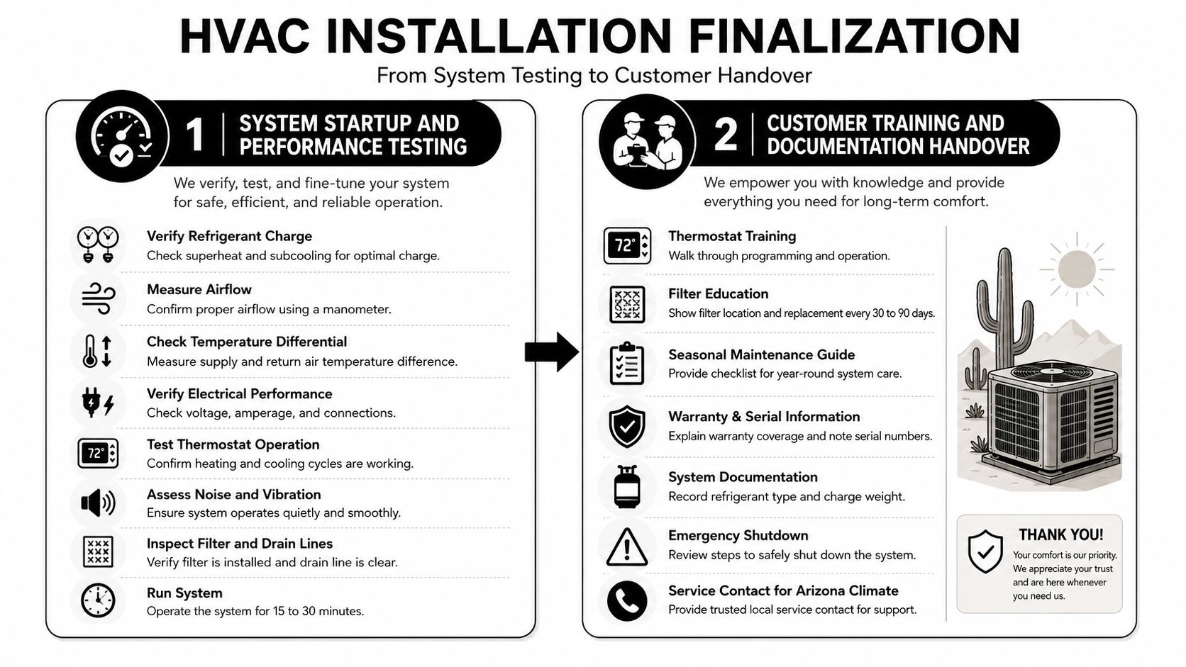
Startup turns installation into measurable performance. Operate the system until conditions stabilize, then record airflow, static pressure, temperature differences, electrical readings, refrigerant measurements, safety-device operation, and control response. Cold air from one register proves very little.
Use the manufacturer's requirements and approved design documents as the acceptance criteria. Measure supply and return airflow, including the farthest outlets and rooms with earlier comfort complaints. Duct leakage belongs in the pass/fail record for a quality installation, not in a list of cosmetic observations. ENERGY STAR's HVAC quality-installation guidance also calls for a complete installation file and ventilation compliance documentation.
Require measured results, not a verbal sign-off
A written startup report gives future service work a usable baseline. Record model and serial numbers, test conditions, refrigerant type and charge, superheat and subcooling where applicable, static pressure, airflow observations, supply and return temperatures, voltage, amperage, safety controls, and thermostat operation.
Check each operating condition:
- Cooling cycle: Verify compressor, condenser fan, indoor blower, controls, and condensate drains.
- Heating cycle: Test furnace ignition and safety operation, or verify heat-pump heating and supplemental heat.
- Airflow: Look for restrictions, abnormal static pressure, room imbalance, blocked returns, and weak delivery at far outlets.
- Commercial operation: Run rooftop equipment through the building's actual sequence where practical, including occupied and unoccupied behavior.
- Refrigeration: For a walk-in cooler, confirm that the box reaches and holds its required operating temperature during sustained demand.
The report should explain what was measured, not merely confirm that the system passed testing.
Resolve a low charge, loose electrical connection, failed float switch, control fault, or airflow restriction before acceptance. For Arizona installations, record performance under the expected cooling demand and confirm that rooftop equipment, split systems, ductless units, and walk-in coolers respond according to their equipment-specific requirements. Without recorded measurements, the owner has no dependable baseline for later diagnosis or maintenance.
10. Customer Training and System Documentation Handover
A successful installation ends with an operator who can use and maintain the system, not with manuals left on a counter. Show homeowners and building staff how to operate the controls, find and replace filters, protect airflow, and recognize conditions that require service. Explain why supply registers, return grilles, drain protection, and safety switches must remain accessible and functional.
The handover file should identify the equipment, installation date, model and serial numbers, warranty terms, permit and inspection records, filter specifications, drain arrangement, service contact, and recorded startup results. Add photographs of concealed components documented before closure. For commercial sites, include an equipment map, control sequence, service clearances, and O&M manuals for each rooftop unit, walk-in cooler, ductless system, or comfort system.
Demonstrate, then verify operator use
Use the installed equipment during training. Show the actual filter and have the operator remove and reinstall it in the correct orientation. Demonstrate normal cooling and heating, thermostat programming, emergency functions, drain protection, and disconnect locations. Ask the operator to repeat the basic tasks before signing the handover.
- Homeowner handover: Review thermostat settings, filter access, outdoor-unit clearance, unusual sounds or odors, and emergency contact procedures.
- Property manager handover: Provide a service log, seasonal inspection plan, equipment labels, and access instructions for technicians.
- Restaurant handover: Cover rooftop access, kitchen schedules, walk-in cooler alarms, door discipline, and response procedures.
- Warranty records: Explain manufacturer coverage, installer coverage, registration duties, and exclusions.
- Maintenance plan: Set inspection and service intervals for filters, drains, ducts, heat pumps, or furnaces based on equipment use and site conditions.
Arizona operators should also receive guidance suited to heavy cooling demand, including outdoor-unit clearance, rooftop access, and signs of reduced performance. Keep equipment-specific instructions separate: split systems need matched indoor and outdoor service information, ductless units need indoor-head and remote-control guidance, rooftop units need access and control-sequence records, and walk-in coolers need alarm and door-response procedures.
The final file should let the owner compare future service findings with the documented installation baseline. Before acceptance, confirm that the customer has the records, can perform the agreed user tasks, and knows who to contact when the system or safety controls require attention.
10-Point HVAC Installation Checklist Comparison
| Item | Implementation Complexity 🔄 | Resource Requirements ⚡ | Expected Outcomes ⭐📊 | Ideal Use Cases 💡 | Key Advantages ⭐ |
|---|---|---|---|---|---|
| System Sizing and Load Calculation | High 🔄🔄🔄, requires Manual J expertise and climate data | Specialized software, trained technician, time | Correct tonnage/BTU, balanced comfort, energy savings 📊 | New construction, additions, full replacements | Prevents over/under-sizing; improves efficiency and warranty compliance |
| Ductwork Design, Sealing, and Air Leakage Control | High 🔄🔄🔄, detailed design and tight sealing required | Materials (mastic/tape/insulation), testing tools, skilled installers ⚡ | Even airflow, reduced losses, better IAQ 📊 | New builds, attic installs, retrofits with high leakage | Consistent comfort, lower energy loss, rebate eligibility |
| Equipment Selection and Compatibility Verification | Medium–High 🔄🔄, matching components and specs | Product research, manufacturer data, installer knowledge ⚡ | Optimal efficiency, valid warranties, reliable performance ⭐📊 | Replacements, heat pump or ductless choices, high-efficiency upgrades | Matched systems run to spec; long-term energy savings |
| Permits, Inspections, and Code Compliance Documentation | Medium 🔄🔄, administrative steps and inspections | Permit fees, inspector time, contractor licensing paperwork ⚡ | Code-compliant installation, protected warranties, legal resale docs 📊 | Any installation requiring jurisdiction approval or resale | Avoids liability, ensures safety and insurance coverage |
| Refrigerant Line Installation and Evacuation | High 🔄🔄🔄, critical procedural precision required | EPA-certified techs, vacuum/pump/recovery gear, copper lines ⚡ | Moisture-free system, correct charge, compressor protection ⭐📊 | Long line runs, mini-splits, new condenser/coil installs | Prevents compressor failure; ensures design efficiency |
| Electrical Connections and Circuit Verification | Medium 🔄🔄, code-focused electrical work | Licensed electrician, appropriate breakers, wiring, disconnects ⚡ | Stable power, reduced tripping, safe operation 📊 | Older homes, high-capacity units, new service installs | Protects equipment; meets NEC and safety standards |
| Drain Line Installation and Condensation Management | Low–Medium 🔄, straightforward but must be correct | PVC/drain pans, traps, float switches, proper routing ⚡ | Prevents water damage and mold; reliable condensate removal 📊 | Attics, basements, high-humidity systems, mini-splits | Protects structure and IAQ; simple preventative safety |
| Thermostat Installation and Control System Setup | Low–Medium 🔄, wiring and placement considerations | Thermostat device (smart option), wiring (C-wire), calibration tools ⚡ | Accurate control, energy automation, remote access ⭐📊 | Retrofits, smart-home integrations, zoned systems | Improves efficiency and user control; supports scheduling |
| System Startup, Testing, and Performance Verification | Medium–High 🔄🔄, comprehensive testing procedures | Gauges, manometer, meters, technician time for run-in ⚡ | Verified performance, baseline measurements, warranty support 📊 | All new installs and major repairs | Catches defects early; documents correct operation |
| Customer Training and System Documentation Handover | Low 🔄, time for walkthrough and paperwork | Printed docs, time for demonstration, basic tools ⚡ | Better user operation, fewer needless service calls, maintained warranties 📊 | All installations, homeowners and building managers | Empowers users; extends equipment life and satisfaction |
Turn the Checklist Into a Signed Handover
A successful HVAC project ends with evidence. Before accepting the installation, confirm that the permit is closed, the equipment is matched, the ductwork is sealed and evaluated, airflow is documented, refrigerant work is complete, electrical readings are acceptable, drains are protected, safety controls operate, and the thermostat or building controls respond correctly. The customer should receive warranty records, model and serial information, the startup report, inspection documentation, filter guidance, maintenance recommendations, and operating training.
That record protects more than comfort. It gives the next service technician a baseline for AC maintenance, quality air conditioning repairs, duct inspection, and future replacement guidance. Without measurements and photographs, a later diagnosis can become a guessing exercise. With them, a technician can compare current airflow, electrical behavior, refrigerant operation, drain performance, and control response against the installation condition.
The equipment-specific closeout also matters:
- Split systems: Confirm the indoor coil and outdoor unit are manufacturer-matched, the line set is protected and evacuated, the condensate drain and secondary pan are secure, and airflow is balanced.
- Ductless mini-splits: Check every indoor head, line-set support, insulation, drain, remote, and zone-control sequence. One correctly operating head doesn't prove that the entire multi-zone system is ready.
- Rooftop units: Verify roof placement, curb or support stability, weather sealing, service access, electrical disconnects, filters, belt or motor condition where applicable, and the commercial operating sequence.
- Walk-in coolers: Confirm sustained-temperature performance, long refrigerant-line installation, defrost and control behavior, door and alarm operation, and adequate drainage during extended cooling.
Arizona owners should also plan for the environment after installation. Dust can load filters and restrict airflow, attic heat can expose weak insulation and sealing, and long cooling runs can reveal charge, electrical, or control problems that a brief startup misses. The right maintenance interval depends on the equipment and site, but a licensed specialist should inspect the system before small defects become an emergency.
Cobre Valley Air LLC serves Globe, Miami, Superior, and surrounding Arizona communities with HVAC repair and installation, duct design and inspection, ductless mini-split work, indoor air-quality services, rooftop-unit maintenance, and walk-in cooler support. Its new-build approach includes load calculations, equipment sizing, airflow planning, startup checks, room-balance review, and a final walkthrough. For homeowners, builders, property managers, restaurants, and commercial operators, that service-focused process keeps the installation record connected to real operating conditions.
Retain the signed handover and startup report. Use them whenever you schedule AC maintenance, request an air-conditioning repair, investigate uneven comfort, evaluate duct leakage, or plan a replacement.
If your Globe, Miami, Superior, or surrounding Arizona property needs a documented AC installation, duct evaluation, heat-pump or furnace setup, rooftop-unit service, or walk-in cooler inspection, Cobre Valley Air LLC can help with code-compliant work and measurable handover checks. Visit Cobre Valley Air LLC to discuss your HVAC installation checklist and schedule the appropriate next step.