


You turn on the shower, wait, adjust the handle, and wait longer. Then the water swings from lukewarm to cold, or the tankless unit fires for a moment and drops out. In most homes, that isn't a “bad tankless” problem. It's an installation diagram problem.
A proper tankless water heater installation diagram does more than show where pipes go. It maps combustion air, vent routing, gas delivery, service clearances, wiring, condensate handling, and fixture demand. Miss one of those, and the homeowner ends up blaming the appliance for an install issue.
That matters in Arizona, where permit review, long fixture runs in larger homes, and tight utility spaces can turn a simple replacement into a code headache. I see the same pattern in mechanical rooms that also carry air conditioning repairs, ac installation work, ac maintenance calls, heat pumps, furnaces, and duct design concerns. Good tradespeople don't treat the water heater in isolation. They look at the whole system, the layout, and how service access will work later.
Introduction and Project Overview
A homeowner usually starts this project for one reason. They're tired of running out of hot water or tired of standing in a shower waiting for the unit to catch up.
That's where a detailed tankless water heater installation diagram earns its keep. Gas and electric units both heat on demand, but they don't install the same way. Gas models depend on correct venting, combustion setup, and fuel delivery. Electric models depend on dedicated power, correct conductor sizing, and clean mounting and wiring. If the diagram is vague, the install gets vague too.
For many homes, the efficiency upside is real. Tankless water heaters achieve a 24% to 34% higher energy efficiency compared to conventional storage tank models for households that use 41 gallons or less of hot water daily, according to AHRI's summary of U.S. Department of Energy guidance. But that gain depends on installing the unit so it can operate the way it was designed to.
A clear diagram answers practical questions before the first tool comes out. Is the vent going horizontal through a wall or vertical through the roof? Does the gas line need to be replaced instead of reused? Is the unit too far from the fixtures to perform well without recirculation? Is there enough room to service it later without pulling other equipment apart?
Field reality: Most tankless complaints I hear after a fresh install come from layout choices, not the heater itself.
If you're still deciding what type of unit fits your house, this guide on how to choose a tankless water heater is a good starting point before you commit to the diagram.
Preparing Your Tankless Water Heater Installation
Preparation decides whether a tankless install passes inspection and performs the way the diagram says it should. I see more trouble from bad planning than bad equipment, especially when a homeowner replaces a standard tank with a high-demand gas unit or a whole-home electric model without checking what the house can support.
Start with the load on the house. A tankless heater has to cover the fixtures that run at the same time, plus the temperature rise your local water conditions demand. In Arizona, that calculation often looks different than a generic online tutorial suggests, and permit reviewers may care just as much about gas sizing, vent routing, or panel capacity as the heater itself.
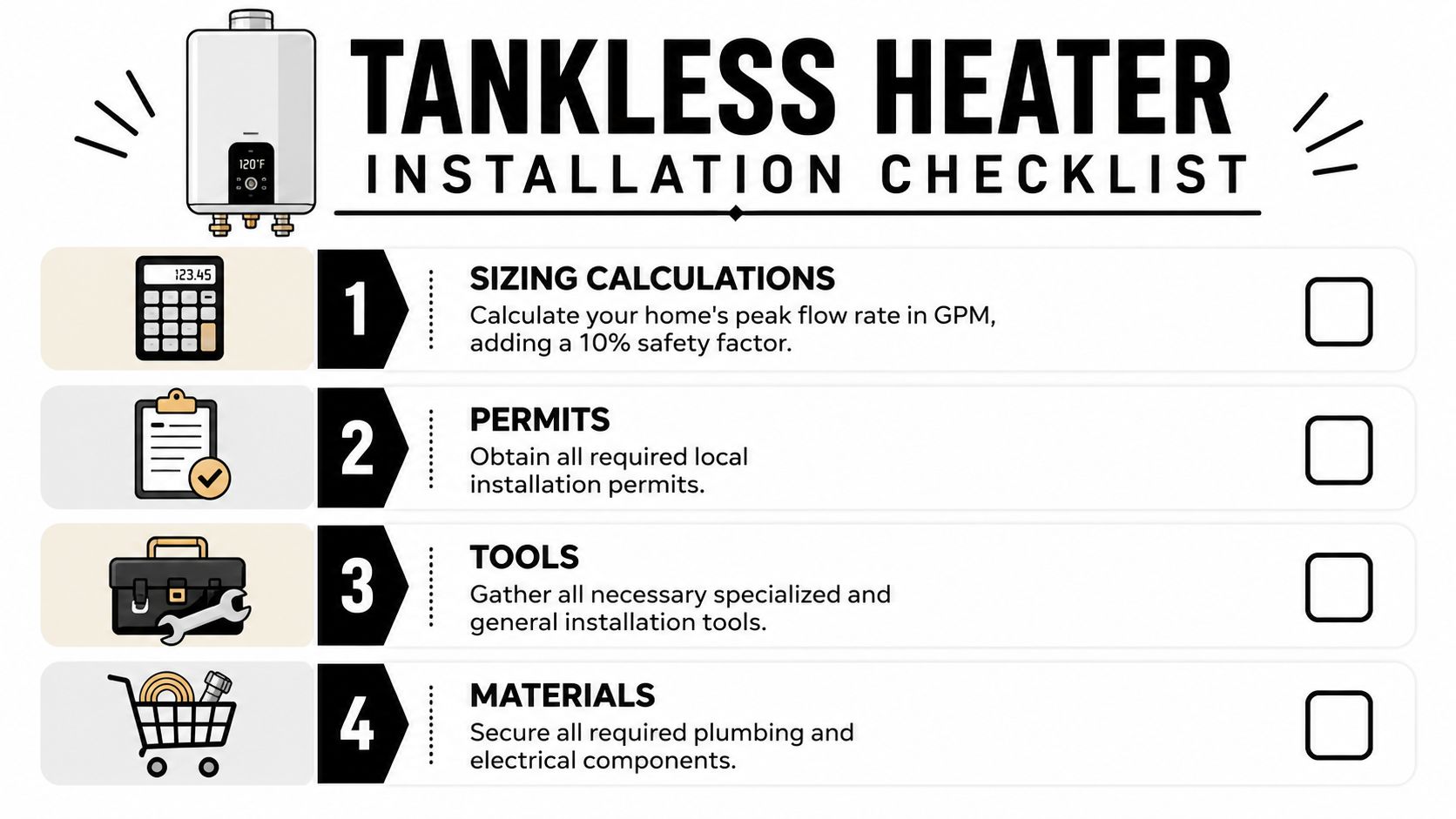
A solid prep routine covers four checks before any mounting marks go on the wall:
Map simultaneous fixture use
List the fixtures that are likely to operate together during the busiest part of the day. Two showers and a washing machine create a very different demand than one bathroom and a kitchen sink.Confirm the unit matches the house
Gas models need enough fuel volume and an approved vent path. Electric models need breaker space, wire sized for the manufacturer's requirements, and a panel that can handle the added load without shortcuts.Choose the location from the diagram backward
Pick the mounting spot based on venting, water line routing, service clearance, drain provisions, and future access. The old tank location works sometimes, but not often enough to assume it is the best choice.Build the permit set before the install date
In Arizona, that usually means matching the manufacturer diagram to the actual house layout, then checking local requirements for vent termination, gas work, electrical changes, and inspection sign-off.
If you are still narrowing down capacity, this guide on what size water heater you need is a useful starting point before you finalize the installation diagram.
Arizona permit and material planning
Permit rules vary by city and county, but the practical rule stays the same. Pull the permit before the work starts if the project changes gas piping, venting, electrical supply, or equipment type. A tank-to-tankless swap often looks simple in the garage and still fails review because the utility demands are completely different.
That matters in Arizona homes where access can be tight, attic temperatures are high, and exterior wall locations may affect vent termination options. Generic tutorials rarely cover that part well. A diagram that works on paper still has to satisfy the inspector and leave enough room for service later. That is one of the places homeowners usually benefit from having Cobre Valley Air review the plan before materials get purchased.
Gather materials from the actual equipment manual and your approved layout, not from a one-size-fits-all shopping list.
For gas installs
Black iron pipe and fittings: often needed when the existing gas line is undersized for the new heater.
Approved vent components: use only the venting system listed by the manufacturer for that model.
Manual shutoff valve and sediment trap parts: common code items that should be planned, not improvised.For water connections
Isolation valves: they make flushing, descaling, and service much easier.
Pipe, fittings, and insulation: match these to the run length, exposure, and pipe material in the house.
Flush plan for the cold line: debris left in the line can create startup problems and damage components.For electric installs
Dedicated circuit materials: breaker, conductor, disconnect method if required, and grounding parts must match the nameplate and manual.
Mounting hardware: wall structure and unit weight matter, especially for garage and utility-room installs.For any install
A full diagram packet: keep the mounting template, piping layout, venting pages, electrical pages, condensate details if applicable, and permit notes together on site.
Good preparation saves time twice. It shortens installation day, and it prevents the common Arizona callback where the heater works, but the vent, gas line, electrical supply, or inspection paperwork does not.
Installing Venting and Piping Using the Installation Diagram
A good annotated diagram makes the mechanical path obvious. You should be able to trace air in, exhaust out, gas in, cold water in, and hot water out without stopping to interpret a messy sketch.
Vent routing that actually works
Gas tankless venting isn't a freestyle exercise. Indoor units must be vented according to the manufacturer's approved pathway, typically vertically through the roof or horizontally through a wall, with the exact routing and separations controlled by the manual and approved vent components. If the vent path gets improvised in the field, performance and safety both suffer.
The first decision is usually simple. Go straight and short whenever the home allows it. Every extra offset, awkward turn, or crowded chase makes the install harder to inspect and harder to service later.
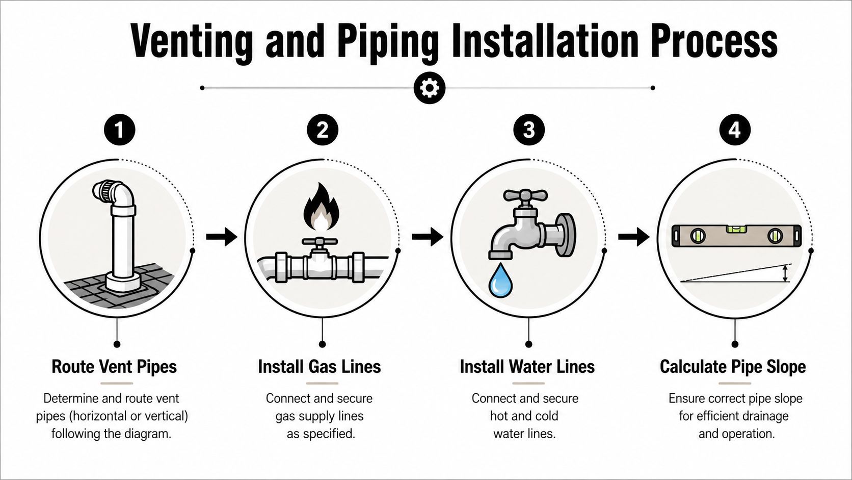
When I lay out venting from a diagram, I'm checking three things first:
Termination path
Can the vent leave the building cleanly without conflicting with windows, walkways, or roof details?Service access
Can a technician still remove covers, test components, and inspect the vent without disassembling half the room?Support and fit
Is there a stable path for the vent material, or will someone be forcing a rigid system through framing that was never planned for it?
A vent layout can pass on paper and still be a bad install if nobody can service the unit after the walls close.
Gas piping and why old lines often fail the new unit
The gas line is where many replacement jobs go sideways. Homeowners look at the old tank line and assume it can stay. That's often wrong.
A 199,000 BTU input tankless unit may require a 1-inch black pipe instead of a ¾-inch line to avoid flame starvation, and a sediment trap 6–12 inches below the inlet is code-mandated to catch particulates, according to this tankless installation guide.
That one fact explains a lot of nuisance issues. If the burner can't get enough fuel, ignition becomes unreliable and combustion quality suffers. On a clean installation diagram, the gas path should show the route from the meter, the shutoff location, and the sediment trap placement before the appliance connection.
A practical gas-side checklist:
Follow the meter-to-unit route
Don't just tie into the nearest branch because it's convenient.Install the manual shutoff where it's accessible
If you have to climb over equipment to reach it, the layout needs work.Place the sediment trap correctly
It belongs in the gas train where it can catch debris before it enters the heater.
Water piping and protecting the heat exchanger
The water side looks easy until debris gets into a new heat exchanger. The diagram should show cold inlet, hot outlet, valves, and any required accessories in the right order.
One step gets skipped all the time. The cold supply line should be flushed before it's connected to the unit. The installation guidance cited earlier specifies flushing the cold supply line for 2 to 3 minutes before connection in order to remove debris that can damage the heat exchanger, as shown in the same installation guidance video.
That's not a cosmetic step. It's protection for one of the most expensive components in the appliance.
A water piping layout works best when it's clean and serviceable:
| Piping point | What the diagram should show |
|---|---|
| Cold inlet | Straight access, valve placement, and flush path |
| Hot outlet | Clear route to the house distribution |
| Service isolation | Room to attach hoses and work safely |
| Insulation points | Long or exposed runs that need heat retention help |
If the home has long fixture distances, a generic diagram may still leave you with poor performance at the tap. That problem shows up later as customer frustration, even though the basic install “looks right.”
Setting Up Electrical Connections and Condensate Drain
Electric tankless installations punish sloppy electrical work fast. There's no room for guessing on conductor size, breaker matching, grounding, or where the unit will sit.
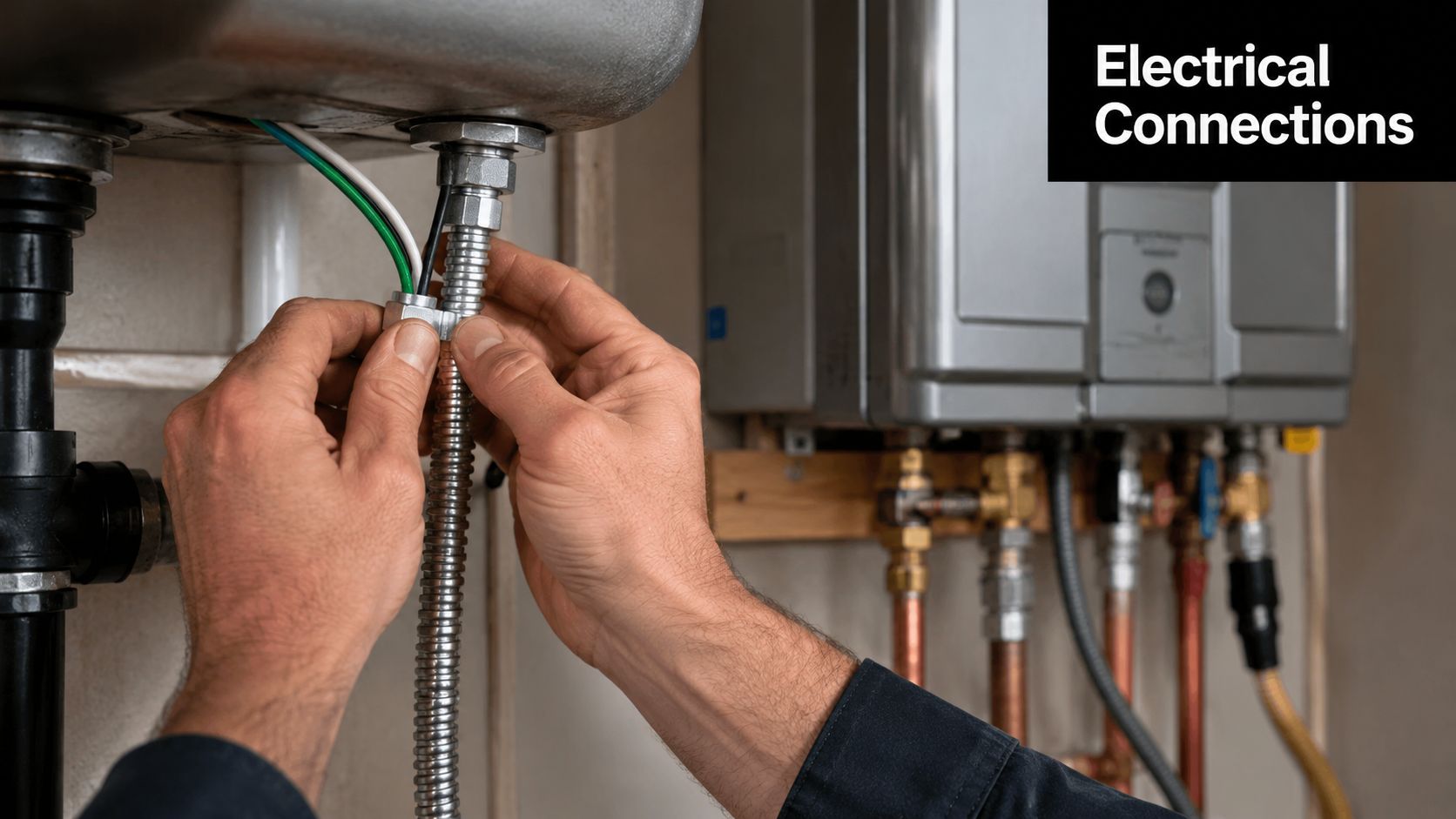
Wiring the unit the way inspectors expect
Electric tankless water heaters require a dedicated 240 V circuit with 8-gauge wire and a separate ground conductor per NEC guidelines to prevent hazards and ensure code compliance, as shown in this electrical requirements document.
That's the first thing I want homeowners to understand. This isn't like swapping a small appliance. The branch circuit has to match the heater's electrical demand, and the diagram needs to identify every required circuit serving the unit.
The physical mounting matters too. The install guidance referenced earlier specifies a dedicated circuit and notes that many units require proper mounting through built-in brackets with appropriate screws into a suitable surface. If the wall is weak, uneven, or crowded by other systems, fix that first.
Here's what a clean electrical setup includes:
Dedicated feeder path
The circuit serves the heater only.Correct conductor and grounding
The wire gauge and separate ground must match the equipment requirements.Protected exposed runs
Areas under sinks or otherwise exposed should be handled with the proper cable protection called for by the installation instructions.Accessible disconnecting means and panel labeling
The next person servicing the unit should know exactly what feeds it.
Condensate drain details that get missed
Condensing units create condensate, and that water has to go somewhere by design, not by accident. The drain path should be planned on the same diagram set as the water and gas work so you don't end up improvising with a trapless or awkward route.
A bad condensate drain usually reveals itself in one of three ways. Dripping where it shouldn't. Backing up into the unit area. Or getting added so late that it blocks service access.
This video gives a helpful visual reference for the connection sequence and layout approach:
Keep the heater near connected equipment when systems share space
In homes where the water heater ties into an air handling unit for combined space and water heating, layout discipline matters even more. The PNNL guidance on integrated heating and hot water systems says the AHU should be positioned as close as reasonably possible to the water heater and that all piping should be insulated to reduce heat loss.
That advice lines up with what works in the field. When mechanical rooms already carry heat pumps, furnaces, and duct design constraints, long unplanned hydronic runs create extra losses and service headaches. Tight, readable diagrams keep everyone honest.
Verifying Required Clearances and Safety Compliance
A tankless install can look clean on day one and still fail inspection or become a service headache a year later if the clearances are wrong. I see that most often in garage corners, laundry closets, and remodels where cabinets or shelving got planned before anyone checked the manufacturer diagram.
As noted earlier in the installation guidance video, many tankless layouts call for about 12 inches above the unit, 24 inches in front, 4 to 6 inches at the sides, and 12 inches below a wall-mounted heater. The exact numbers still come from the model's manual, not a generic sketch, and that matters because gas and electric units do not always have the same service and venting constraints.
Clearance Requirements for Tankless Water Heaters
| Location | Minimum Clearance |
|---|---|
| Top | 12 inches |
| Front | 24 inches |
| Sides | 4 to 6 inches |
| Bottom for wall-mounted units | 12 inches |
Those spaces protect more than airflow. They give a technician room to remove the cover, test components, inspect the venting, and service isolation valves without pulling the whole installation apart. Homeowners sometimes want the unit tucked tighter for appearance. The trade-off is harder maintenance and a greater chance of failing final inspection.
Arizona jobs add another layer. Local enforcement can vary by jurisdiction, especially on vent termination, combustion air, and where the unit sits relative to doors, windows, and property lines. A diagram that works in a generic online tutorial may still need changes to pass in Globe, Miami, or nearby service areas.
Final safety checks worth doing before inspection
Check the finished install the way an inspector or service tech will.
Gas leak check
Test every gas joint with an approved method before startup and again after the burner has operated.Venting review
Confirm the vent route, support, termination, and material match the manufacturer requirements and local code.Combustion and ignition check
Watch the heater light off and run under demand. Delayed ignition, unstable flame, or repeated lockouts usually point to a setup problem that should be corrected before sign-off.Service access check
Make sure valves, cleanouts, electrical disconnects, and the front cover can all be reached without removing building finishes or stored items.
Good installs stay readable with the cover off.
If you want the local paperwork side explained in plain language, Cobre Valley Air's Arizona water heater replacement permit guidance helps clarify when permits and inspections apply, and when it makes sense to hand the job to a licensed crew.
Troubleshooting Common Mistakes and When to Call Cobre Valley Air
Most failed tankless jobs don't fail because the installer forgot how to sweat copper or land a wire. They fail because one decision upstream was wrong and everything downstream reflected it.
A common example is the large Arizona home with long fixture runs. Generic diagrams often omit recirculation loop sizing for long pipe runs over 30 feet, leading to premature shut-offs and inconsistent temperatures in large homes, as shown in this video discussion of long-run tankless issues. That's exactly how homeowners end up with the cold water sandwich problem after a technically “complete” install.
Mistakes that usually show up after startup
Some errors reveal themselves immediately. Others wait until the homeowner starts using the system normally.
Undersized gas piping
The unit lights poorly, drops flame, or acts erratic under higher demand.Incorrect vent path
The heater may lock out, perform inconsistently, or raise inspection concerns.Loose or incomplete electrical work
Electric units become unreliable fast when a dedicated circuit or correct grounding wasn't handled properly.Missing recirculation strategy in large homes
The heater itself may be fine while delivery at the fixtures is not.
When DIY stops making sense
There's a line between homeowner-friendly prep and work that should move to a licensed technician. That line comes sooner when the project includes gas repiping, panel work, vent rerouting, remodel coordination, or permit correction after a failed inspection.
Call a pro when:
The replacement changes fuel demand
If the old piping may not support the new appliance, guessing is expensive.The home has long hot water runs
Generic diagrams won't solve delivery issues in a larger layout.Multiple trades share the space
Water heater work around ac installation, heat pumps, furnaces, and duct design needs coordination so one fix doesn't block another system.You need the job to pass cleanly
If inspection, startup, and long-term serviceability matter, the diagram has to match the installation, not just the box contents.
A tankless water heater installation diagram should reduce uncertainty. If yours leaves open questions about gas sizing, recirculation, venting, or electrical requirements, that's the point to stop and bring in someone who works these systems every week.
If your tankless project involves permit questions, long pipe runs, gas line changes, or a mechanical room crowded with heating and cooling equipment, Cobre Valley Air LLC can help with code-compliant installation, diagnostics, and replacement work across Globe, Miami, Superior, and nearby Arizona communities.